2000 Series Installation and Operation
5
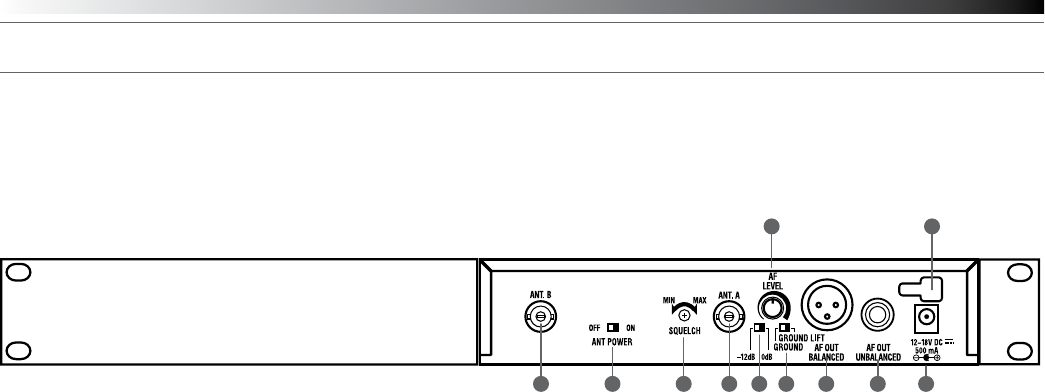
Fig. D – Rear Panel Controls and Functions
10. ANTENNA INPUT JACK: BNC-type antenna connector for
Tuner “B.” Attach the antenna directly, or extend it with a low-loss
antenna cable. See the “Antennas” section on page 3 for more
details.
11. ANTENNA POWER SWITCH: Two-position switch turns on/off the
12V DC antenna power for use with powered antennas or
accessories. Factory setting is off. See the “Antennas” section on
page 3 for more details.
12. SQUELCH CONTROL: Adjusts level of noise-muting circuit (preset
at factory but can be adjusted as circumstances warrant). Factory
setting is full counterclockwise (minimum).
13. ANTENNA INPUT JACK: Input for Tuner “A.” Attach the supplied
antenna directly, or extend it to an accessory antenna with a low-
loss antenna cable.
14. AF OUTPUT ATTENUATOR: Two-position switch adjusts audio output
level of the balanced (XLR) audio output jack with attenuation of
0 dB or –12 dB. Factory setting is 0 dB.
15. AF LEVEL CONTROL: Adjusts audio output level of both AF output
jacks. Factory setting maximum output—fully clockwise.
16. GROUND LIFT SWITCH: Disconnects the ground pin of the
balanced output jack (15) from ground. Normally, the switch should
be to the left (ground connected). If hum caused by a ground loop
occurs, slide switch to the right (ground lifted). Factory setting is
ground connected.
17. BALANCED AUDIO OUTPUT JACK: XLRM-type connector. A
standard 2-conductor shielded cable can be used to connect the
receiver output to a balanced microphone-level input on a mixer or
integrated amplier.
18. UNBALANCED AUDIO OUTPUT JACK:
1
/
4
" phone jack. Can be
connected to an unbalanced aux-level input of a mixer, guitar amp or
tape recorder.
19. POWER INPUT JACK: Connect the DC plug from the included in-line
AC adapter.
20. CORD HOOK: Loop the small DC cord around the cord hook to keep
the DC plug from pulling out accidentally.
10 11 13 1412 1716 18 19
15 20


 (120 pages)
 Manymanuals.com
 Manymanuals.de
 Manymanuals.fr
 Manymanuals.it
 Manymanuals.pl
 Manymanuals.cz
 Manymanuals.es
 Manymanuals-pt.com
Comments to this Manuals